

Troubleshooting Guide
If you are having difficulty with one of our devices or sensors please review the guide below.
If you still have questions or difficulties not covered in this guide scroll to the bottom of the page and send us a message, we will resolve your issue as soon as we can. If you require immediate help you can call our technical support line from 2:00 pm to 6:00 pm Monday through Thursday.
If the problem persists we can arrange to repair the device. Repairs for any GP devices are $150 flat rate, return shipping included, and this charge does not cover mechanical damage. This charge does not cover the CO2 Gas Analyzer, which will be priced depending on the nature of the issue.
We repair older C2 units from J&J ENGINEERING, costs will be quoted.
User Manual and Tutorial Videos
While the full manual for each device is available under the “Help” menu in any software download, we have provided a downloadable manual for the GP-8 (the software basics included will also cover the GP-4/12 as well):
We have also created a couple video tutorials to help you get started:
Amp Testing for ECG, EMG, and EEG
Most microvolt level signal problems are poor skin prep or insufficient moisture between the electrode and skin.
How to test the amp unit input for correct operation:
Connect 3 leads to the +, -, and ground inputs of one channel.
Start an application and click on a raw signals screen.
Check the instruments indicator light, it must be on steady (not blinking).
Short the 3 snap leads or electrodes together, a paper clip works for this.
After 30 seconds the signal graph display will be near zero (under 10uV).
Moving the leads should show a corresponding motion on the graph.
If the above is successful, the unit is working and the leads are good.
Notes:
If the signal graph jumps top to bottom screen or stays at zero, it may be a bad lead wire. Replace all three wires and try test again.
If the green indicator is blinking, the computer is not communicating with the unit. This may be the software, computer or an instrument problem.
Signals displayed with no leads or poor electrode connection have no test value. The signal shown can be completely different day to day dependent on environmental electrical noise and nearby radio signal sources.
High signal levels with well prepped electrodes or shorted leads is either a broken lead wire or high local electrical noise. To minimize noise keep leads and amp close to subject and away from computer and all other wires. If high noise continues, try a new location. It is impossible to work in some locations.
Sometimes noise comes from a laptop power supply, try running it on battery.
Local noise sources can sometimes be traced with an AM battery radio set between stations. The radio noise will increase as it gets close to the source. Problems have come from wall switches, thermostats, light fixtures, and equipment with motors.
Signal and Sensor Hookup and Problem Solver
ECG Raw Signal and FFT Display Interpretation
Skin must be oil free, clean and wet for a good electrode contact. Keep electrode leads close to the body and away from other wires. A noise source may be close by. Try a different location. Move the computer and monitor away from the amp and sensors
Normal ECG on the check signal screen, heart rate values will be accurate:
This ECG has power line interference from poor electrode prep:


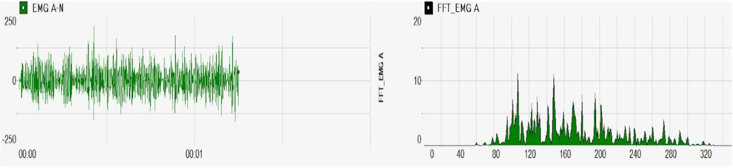
EMG Raw Signal and FFT Display Interpretation
Twist the positive and negative leads together like a rope. Move the amp and leads closer to the subject. Check that no other wires are near the EMG leads. EMG is more affected by poor electrode prep than ECG, the signal is much smaller.
Normal EMG signal on the check signal screen:
Abnormal EMG with power line harmonics overpowering the EMG:

PPG Optical Finger Pulse Sensor
This sensor measures blood volume in the finger tip. The volume increases with each heart beat, then decreases between beats. The peak to peak time can be converted to heart rate and the amplitude to the blood volume signal.
Common problems:
Cable connector not fully inserted on instrument.
Hand motion causes noise in the signal.
Normal PPG raw signal and a PPG graph that starts when the ECG R wave is detected.


Skin Conductance and Skin Resistance
A problem with SR/SC is always the leads or electrodes. Test the leads by shorting the snaps together. If the SR reading goes down near zero or SC goes high, then the unit and leads are good. The conductive surface can be rubbed off the sensors by too much cleaning. The best way to test electrodes is to try new ones. Be sure the fingers are very damp when the two sensors are placed. If this does not produce a signal on the graph screens after 5 minutes , replace the SE-35 sensors with new ones. This measurement can also be made with ECG type disposable sensors if both are the same type. SR/SC will only work if fingers are moist and oil free.
SC=Skin Conductance measured in microSiemens (uS)
SR=Skin Resistance measured in Ohms or K Ohms
1uS=1,000,000 Ohms=1,000 K ohms
10uS=100,000 Ohms=100 K ohms
SC is used for recording as the numbers are smaller. A lower value indicates a more relaxed state.
Both SC and SR are the same signal displayed with different units. SR goes up with relaxation and SC goes down. SCR (skin conductance response) is short term Positive or Negative signal change.
GSR (galvanic skin response) or EDA (electrodermal activity) are other terms for the SC measurement.
Contact us for more detailed technical support
Product Return Policy
A 30 day period starting at time of delivery is the limit for returns. The product must be returned to J&J Manufacturing by prepaid common carrier. Signature required shipments will not be accepted. The tracking number must be sent to physiocomdesign@gmail.com. After the product is received and inspected, a refund amount will be calculated. The value of consumables and sensors showing use will be deducted from the refund. A refund will be made to the credit card used for the purchase.